Beyond the Die: Verifying the Connected Chip
Source: https://semiwiki.com/eda/siemens-eda/374270-beyond-the-die-verifying-the-connected-chip/
One of the standout presentations at the 2026 TSMC OIP Forum highlighted a collaboration between Siemens EDA, Marvell, and TSMC. I always appreciate EDA presentations that bring together customer and foundry perspectives, and this one did not disappoint. We follow 3D IC technology closely and have published more than 150 blogs on the topic over the past three years. As chiplet adoption accelerates, I fully expect SemiWiki to publish twice that many over the next three, absolutely.
2026년 TSMC OIP 포럼에서 가장 주목받았던 발표 중 하나는 지멘스 EDA(Siemens EDA), 마블(Marvell), 그리고 TSMC 간의 협력을 조명한 것이었습니다. 고객과 파운드리의 관점을 한데 모으는 EDA 발표들을 평소에도 매우 높이 사는데, 이번 발표 역시 기대를 저버리지 않았습니다. 저희는 3D IC 기술을 면밀히 추적해 왔으며, 지난 3년 동안 이 주제와 관련해 150개가 넘는 블로그 글을 발행했습니다. 칩렛 채택이 가속화됨에 따라, 세미위키(SemiWiki)가 향후 3년 동안 그 두 배에 달하는 글을 발행하게 될 것임을 저는 절대적으로 확신합니다.
Advanced packaging is changing what it means to verify a chip. As semiconductor designers assemble multiple dies into increasingly complex systems, reliability can no longer be established by checking each component independently. The presentation, “Efficient, Scalable Methodology for Reliability and ESD Verification of Complex 3D IC CoWoS Systems” describes how Marvell and Siemens are addressing that challenge through automated verification of the complete assembly.
고급 패키징(Advanced packaging)은 칩 검증(Verification)이 의미하는 바를 바꾸어 놓고 있습니다. 반도체 설계자들이 여러 다이(Die)를 점점 더 복잡한 시스템으로 조립함에 따라, 각 부품을 독립적으로 검사하는 것만으로는 신뢰성을 확립할 수 없게 되었습니다. "복잡한 3D IC CoWoS 시스템의 신뢰성 및 ESD 검증을 위한 효율적이고 확장 가능한 방법론(Efficient, Scalable Methodology for Reliability and ESD Verification of Complex 3D IC CoWoS Systems)"이라는 제목의 이 발표는 마블과 지멘스가 전체 조립체에 대한 자동화된 검증을 통해 이 과제를 어떻게 해결하고 있는지 설명합니다.
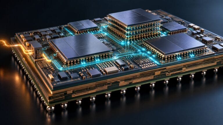
The shift reflects a broader change in semiconductor architecture. Instead of placing every function on one large die, designers can distribute functions across smaller dies, selecting technologies suited to each task. TSMC’s Chip on Wafer on Substrate, or CoWoS, technology supports this approach. The potential benefits include improved performance, lower power consumption, better manufacturing economics, and greater flexibility in combining different technologies.
이러한 변화는 반도체 아키텍처의 광범위한 변화를 반영합니다. 모든 기능을 하나의 거대한 다이에 집어넣는 대신, 설계자들은 기능을 더 작은 다이들로 나누어 각 작업에 적합한 기술을 선택할 수 있습니다. TSMC의 CoWoS(Chip on Wafer on Substrate) 기술은 이러한 접근법을 뒷받침합니다. 잠재적 이점으로는 향상된 성능, 낮은 전력 소비, 더 나은 제조 경제성, 그리고 서로 다른 기술을 결합하는 데 있어 더 큰 유연성이 있습니다.
But dividing a design creates new dependencies. Electrical connections now extend through dies, bumps, interposers, and substrates. A component that passes its own verification checks may still participate in an unsafe protection path once assembled with other components. The essential question becomes whether the entire system works together under the conditions its protection circuitry must withstand.
하지만 설계를 쪼개면 새로운 종속성이 생겨납니다. 전기적 연결이 이제 다이, 범프(Bump), 인터포저(Interposer), 그리고 기판을 관통하여 확장되기 때문입니다. 개별 검증 통과를 거친 부품이라도 다른 부품들과 조립되었을 때는 안전하지 않은 보호 경로의 일부가 될 수 있습니다. 핵심적인 질문은 보호 회로가 견뎌야 하는 조건 하에서 전체 시스템이 유기적으로 함께 작동하는지 여부가 됩니다.
Electrostatic discharge, or ESD, illustrates the problem. Protection structures must provide suitable paths for discharge current, with sufficiently low resistance and adequate current carrying capacity. In a multidie assembly, the structure protecting a vulnerable circuit may reside on another die. Different dies can also have different protection schemes, manufacturing processes, and ESD requirements. Their individual qualifications therefore cannot substitute for checking the assembled protection network.
정전기 방전(Electrostatic discharge, ESD)은 이 문제를 잘 보여줍니다. 보호 구조는 충분히 낮은 저항과 적절한 전류 허용량을 가지며 방전 전류를 위한 적절한 경로를 제공해야 합니다. 멀티다이(Multidie) 조립체에서는 취약한 회로를 보호하는 구조가 다른 다이에 위치할 수 있습니다. 또한 다이마다 보호 체계, 제조 공정, 그리고 ESD 요구 사항이 다를 수 있습니다. 따라서 개별 다이의 적합성 인증이 조립된 보호 네트워크의 검증을 대신할 수는 없습니다.
The methodology presented combines individual die verification with system level analysis. Each die is first checked using Siemens Calibre PERC and applicable foundry rule decks. Assembly information then supports Calibre 3D PERC checks across the integrated system. This preserves the value of established die verification while extending analysis to the connections and interactions introduced by advanced packaging.
제시된 방법론은 개별 다이 검증과 시스템 수준 분석을 결합합니다. 먼저 지멘스 캘리버(Siemens Calibre) PERC와 해당 파운드리 룰 덱(Rule decks)을 사용하여 각 다이를 검사합니다. 그런 다음 조립 정보를 바탕으로 통합 시스템 전반에 걸쳐 캘리버 3D PERC 검사를 수행합니다. 이는 기존 다이 검증의 가치를 보존하는 동시에, 고급 패키징이 도입하는 연결과 상호작용으로 분석 범위를 확장합니다.
Three areas receive particular attention: protection topology, point to point resistance, and current density. Topology checks establish whether required protection structures exist and connect as intended. Resistance checks assess whether discharge paths meet specified limits. Current density analysis evaluates whether the interconnect can carry the required current without exceeding its allowable capacity. Together, these checks address both the organization of the protection network and the physical adequacy of its paths.
특히 세 가지 영역에 주목합니다. 보호 토폴로지(Topology), 점대점(Point-to-point) 저항, 그리고 전류 밀도(Current density)입니다. 토폴로지 검사는 필요한 보호 구조가 존재하며 의도대로 연결되어 있는지 확인합니다. 저항 검사는 방전 경로가 지정된 한계를 충족하는지 평가합니다. 전류 밀도 검사는 상호 연결이 허용 용량을 초과하지 않고 필요한 전류를 흘려보낼 수 있는지 평가합니다. 이 검사들은 함께 보호 네트워크의 구성과 경로의 물리적 적절성 모두를 다룹니다.
Scale makes automation essential. One package ball can connect through multiple bumps and branches, producing many possible paths to analyze. Including substrate, interposer, and die contributions increases computational complexity. Engineers also need debugging tools that identify which layers or connections contribute to a violation, so they can locate the cause and make an informed design change.
규모가 커질수록 자동화는 필수적입니다. 하나의 패키지 볼은 여러 범프와 분기를 통해 연결될 수 있으며, 분석해야 할 수많은 잠재적 경로를 만들어냅니다. 기판, 인터포저, 그리고 다이의 기여도를 모두 포함하면 계산 복잡성이 더욱 증가합니다. 또한 엔지니어들은 위반을 유발한 레이어이나 연결이 무엇인지 식별하여 원인을 파악하고 정보에 입각한 설계 변경을 내릴 수 있는 디버깅 도구가 필요합니다.
The speakers describe an earlier workflow involving separate die checks, manual interface verification, and manual debugging that could take two to three weeks. Their automated approach brings die and assembly information into a holistic verification flow. The transcript does not provide a measured replacement runtime, but it clearly identifies the objective: reduce manual effort and improve the consistency of complex system checks.
발표자들은 개별 다이 검사, 수동 인터페이스 검증, 그리고 수동 디버깅을 포함하여 2~3주가 소요되던 과거의 워크플로를 설명합니다. 이들의 자동화된 접근 방식은 다이와 조립 정보를 통합적인 검증 플로우로 끌어들입니다. 강연 대본에는 실제 측정한 대체 소요 시간이 명시되어 있지 않지만, 목표는 명확합니다. 즉, 수동 노력을 줄이고 복잡한 시스템 검사의 일관성을 향상시키는 것입니다.
Why this matters extends beyond verification productivity. AI infrastructure depends on powerful compute systems and the high bandwidth connections that allow accelerators to cooperate. Advanced packaging helps enable those systems, but integration also concentrates value and risk within each assembly. A protection failure can compromise a package containing multiple otherwise functional dies.
이것이 중요한 이유는 검증 생산성을 넘어섭니다. AI 인프라는 강력한 연산 시스템과 가속기들이 서로 협력할 수 있게 해주는 고대역폭 연결에 의존합니다. 고급 패키징은 이러한 시스템을 가능하게 돕지만, 통합은 또한 각 조립체 내에 가치와 위험을 집중시킵니다. 보호 회로의 고장은 그 외에는 정상 작동하는 여러 다이를 담고 있는 패키지 전체를 손상시킬 수 있습니다.
The presentation’s hypothetical yield example makes that exposure tangible. If ten components each have a 99 percent success probability, their combined probability is roughly 90 percent, assuming independent outcomes. This illustrates compounding risk, rather than predicting manufacturing yield. It reinforces the need to catch integration problems early. Finding those problems before fabrication can also prevent costly redesigns and protect schedules for products with demanding requirements.
발표에서 가정한 수율 예시는 이러한 위험 노출을 구체적으로 보여줍니다. 10개의 부품이 각각 99퍼센트의 성공 확률을 가진다면, 독립적인 결과라고 가정할 때 이들의 결합 성공 확률은 대략 90퍼센트가 됩니다. 이는 제조 수율을 예측하는 것이 아니라 누적되는 위험(Compounding risk)을 보여줍니다. 이는 통합 문제를 조기에 잡아내야 할 필요성을 더욱 강조합니다. 제작 전에 이러한 문제를 발견하면 비용이 많이 드는 재설계를 방지하고 까다로운 요구 사항을 가진 제품의 출시 일정을 보호할 수 있습니다.
Bottom line: The broader lesson is organizational as well as technical: reliability and ESD specialists should participate from the beginning. Effective verification requires rules matched to the assembly, clear protection requirements, and visibility across component boundaries. As chips become systems, verification must follow.
요약하자면: 더 넓은 교훈은 기술적인 면뿐만 아니라 조직적인 면에도 있습니다. 신뢰성과 ESD 전문가들은 처음부터 참여해야 합니다. 효과적인 검증에는 조립에 맞춘 규칙, 명확한 보호 요구 사항, 그리고 부품 경계를 가로지르는 가시성이 필요합니다. 칩이 시스템이 되어감에 따라, 검증 역시 진화해야 합니다.