LLM-assisted schematic test-report analysis and root-cause investigation
By Piyush Bag
Intro: In this AI era, building data centers has become crucial not just for hyperscalers, but for many companies as well, as they build the infrastructure for AI. At a high level, a data center includes compute, storage, networking, and other infrastructure. This article is about the design lifecycle of network hardware.
소개: 이 AI 시대에 데이터 센터 구축은 하이퍼스케일러뿐만 아니라 AI 인프라를 구축하는 많은 기업에게도 매우 중요해졌습니다. 거시적으로 볼 때 데이터 센터는 연산(compute), 스토리지, 네트워킹 및 기타 인프라를 포함합니다. 이 글은 네트워크 하드웨어의 설계 라이프사이클에 관한 것입니다.
Definition: What is a schematic test report generator?
Broadly, when a data center network switch is manufactured, designing the PCB board is a crucial part of the initial phase of the hardware development lifecycle, as it determines which components are required and compatible with customer requirements. The Hardware Design Engineer designs the schematic diagram in CAD software like Cadence Allegro. The schematic is a symbolic connectivity model showing components, nets, pins, ports, hierarchy, and design relationships. The schematic design database is maintained in its native format and can be exported as a PDF for review. The BOM and netlist are stored separately. To verify the schematic diagrams are correct, they run a set of topology tests to ensure basic to advanced design configurations are done correctly. In organizations where git practice is not followed in the hardware development lifecycle and work iteratively, they tend to rely on manually running the topology test, aggregating the log results from the CLI, then viewing the errors, consolidating and manually triaging the errors in a Google Doc with log links and headers only, and placing this doc in the drive for the team to pick up. This process continues until the hardware design engineers ensure all topology tests have passed based on their schematic design. This process matters because it saves a lot of money in the early phase before manufacturing, since errors are caught before production, but it also slows the development lifecycle.
대략적으로 데이터 센터 네트워크 스위치가 제조될 때, PCB 기판 설계는 하드웨어 개발 라이프사이클의 초기 단계에서 매우 중요한 부분입니다. 이는 어떤 부품이 필요한지, 그리고 고객 요구사항과 호환되는지를 결정하기 때문입니다. 하드웨어 설계 엔지니어는 케이던스 앨레그로(Cadence Allegro) 같은 CAD 소프트웨어로 회로도(schematic)를 설계합니다. 회로도는 부품, 넷(net), 핀, 포트, 계층 구조, 그리고 설계 관계를 보여주는 기호학적 연결 모델입니다. 회로도 설계 데이터베이스는 고유 형식으로 유지되며 검토를 위해 PDF로 내보낼 수 있습니다. BOM(부품 명세서)과 넷리스트(netlist)는 별도로 저장됩니다. 회로도가 올바른지 검증하기 위해 엔지니어들은 일련의 토폴로지 테스트를 실행하여 기본부터 고급 설계 구성까지 올바르게 완료되었는지를 확인합니다. 하드웨어 개발 라이프사이클에서 깃(git) 관행을 따르지 않고 반복적으로 작업하는 조직에서는, 토폴로지 테스트를 수동으로 실행하고, CLI에서 로그 결과를 취합한 뒤, 에러를 확인하고, 로그 링크와 헤더만 포함된 구글 문서(Google Doc)에 에러를 통합 및 수동으로 분류(triage)한 후, 팀이 가져갈 수 있도록 이 문서를 드라이브에 올리는 방식을 따르는 경향이 있습니다. 이 과정은 회로도 설계를 바탕으로 모든 토폴로지 테스트가 통과되었다고 하드웨어 설계 엔지니어가 확신할 때까지 계속됩니다. 이 프로세스가 중요한 이유는 제조 전 초기 단계에서 에러를 사전에 잡아냄으로써 많은 비용을 절약할 수 있게 해주지만, 동시에 개발 라이프사이클을 늦추기 때문입니다.
Problem: Why was the schematic test report generator not enough?
In this iterative approach to designing schematic diagrams, running topology tests works fine until the scale is small. Still, as the organization grew, faster iteration alone wasn’t enough, as it could lead to more errors and more back-and-forth in the design phase of the cycle, compared with the hardware requirement document. Another problem was manually aggregating logs from various databases, grouping failures, and matching errors to schematic diagrams in PDF format stored in a centralized repository like Mercury or Perforce; then pasting one error result at a time into a document, formatting it properly, and filling in comments by the hardware design engineer. This solution takes a lot of time, and at this scale it’s hard to iterate quickly as design requirements get bigger and more complex.
회로도를 설계하는 이러한 반복적 접근 방식은 규모가 작을 때는 토폴로지 테스트 실행에 문제가 없습니다. 하지만 조직이 성장함에 따라 더 빠른 반복 작업만으로는 충분하지 않았는데, 하드웨어 요구사항 문서와 비교했을 때 설계 단계에서 더 많은 오류와 반복적인 왕복 작업(back-and-forth)을 유발할 수 있기 때문입니다. 또 다른 문제는 다양한 데이터베이스에서 로그를 수동으로 취합하고, 실패 사례들을 그룹화하며, 머큐리(Mercury)나 퍼포스(Perforce) 같은 중앙 집중식 저장소에 저장된 PDF 형식의 회로도와 에러를 대조하는 것이었습니다. 그 후 에러 결과 하나하나를 문서에 붙여넣고, 적절히 서식을 지정하며, 하드웨어 설계 엔지니어의 코멘트를 채워 넣어야 했습니다. 이 솔루션은 많은 시간이 소요되며, 설계 요구사항이 더 커지고 복잡해지는 현재의 규모에서는 빠르게 반복 작업을 수행하기 어렵습니다.
Solution: Framework to write evals for LLM-based schematic test report analyzer
One managerial solution is to pivot the development approach rather than follow a classic waterfall/iterative hardware development model, and to stay agile / more agentic with modern automation. However, changing the entire development lifecycle is difficult for organizations that have operated in a specific way for years. However, being AI-native from day one is not the only way for hardware engineering to speed up development; integrating and automating with AI plays an important role in such organizations.
관리적 측면의 한 가지 해결책은 고전적인 폭포수/반복형 하드웨어 개발 모델을 따르는 대신 개발 접근 방식을 전환하고, 최신 자동화를 통해 애자일(agile)하게 또는 더 에이전틱(agentic)하게 유지하는 것입니다. 그러나 특정 방식으로 수년간 운영해 온 조직에게 전체 개발 라이프사이클을 바꾸는 것은 어려운 일입니다. 하지만 하드웨어 엔지니어링이 개발 속도를 높이기 위해 첫날부터 AI 네이티브여야만 하는 것은 아닙니다. 이러한 조직에서는 AI를 통합하고 자동화하는 것이 중요한 역할을 합니다.
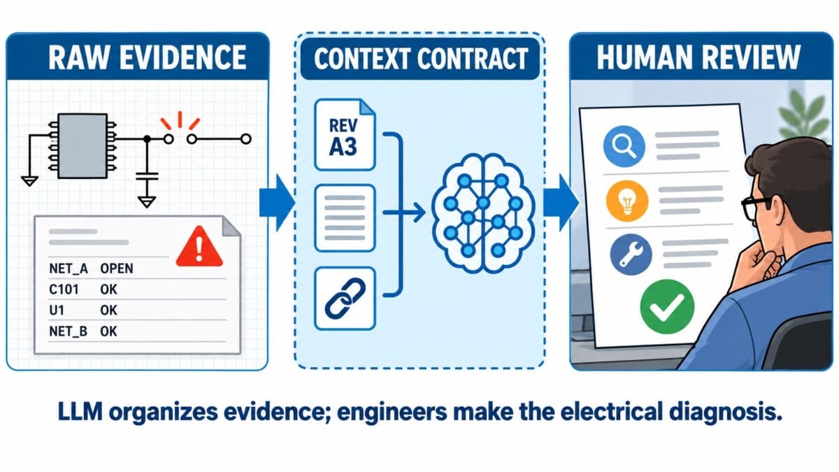
The existing SRG collects schematic revisions, topology test results, job information, raw logs, nets, pins, and component references, and feeds them to an LLM that analyzes and helps explain and organize grouped topology-test results. This information is normalized into structured context and examples that guide the analyzer on what to group and how, written in Markdown with examples and exceptions.
기존의 SRG는 회로도 리비전, 토폴로지 테스트 결과, 작업 정보, 원시 로그, 넷, 핀, 부품 레퍼런스를 수집하여 LLM에 공급하며, LLM은 이를 분석하고 그룹화된 토폴로지 테스트 결과를 설명하고 정리하는 데 도움을 줍니다. 이 정보는 분석기에게 무엇을 어떻게 그룹화해야 하는지 안내하는 구조화된 컨텍스트와 예시로 정규화되며, 예시와 예외 사항이 포함된 마크다운(Markdown)으로 작성됩니다.
Step two in the system is to create a separate context for every failure group, like “missing connection on the VOUT net”, “unconnected power pin”, “repeated topology mismatch” ie. several components such as U29, U57, and U33 may fail the same connectivity rule because they share a common control signal or expected circuit structure. The best part of the LLM-based analyzer is that it explains the result and recommends how to fix the root cause; for example, the engineer might need to inspect the schematic connection, verify the component library, or rerun a specific topology test. To ensure the LLM output is correct, it is compared with a golden dataset of previously reviewed schematic test cases in JSON format.
시스템의 두 번째 단계는 "VOUT 넷의 누락된 연결", "연결되지 않은 전원 핀", "반복되는 토폴로지 불일치" 등 각 실패 그룹에 대해 별도의 컨텍스트를 만드는 것입니다. 즉, U29, U57, U33 같은 여러 부품이 공통 제어 신호나 예상 회로 구조를 공유하기 때문에 동일한 연결 규칙에서 실패할 수 있습니다. LLM 기반 분석기의 가장 큰 장점은 결과를 설명하고 근본 원인을 해결하는 방법을 추천해 준다는 점입니다. 예를 들어, 엔지니어는 회로도 연결을 검사하거나, 부품 라이브러리를 검증하거나, 특정 토폴로지 테스트를 다시 실행해야 할 수 있습니다. LLM 출력이 올바른지 확인하기 위해, 이 출력은 JSON 형식으로 된 이전에 검토된 회로도 테스트 케이스의 골든 데이터셋(golden dataset)과 비교됩니다.
Conclusion: An LLM-assisted schematic report generator can help hardware design teams reduce the manual effort involved in reviewing topology test results. It can organize information from the schematic revision, test logs, and component references and convert it into a report that is easier for the engineer to use, increasing designer productivity. The hardware design engineer still needs to make the final decision about the schematic design and the electrical root cause after reviewing the original schematic and test results. With LLM analysis as just phase one, the process becomes more agentic if traditional CAD tools start providing official MCPs to take actions in the tool based on topology test results; just as software engineers are “vibing,” hardware design engineers will soon “vibe design and test” too.
결론: LLM 보조 회로도 리포트 생성기는 하드웨어 설계 팀이 토폴로지 테스트 결과 검토에 수반되는 수작업 노력을 줄이는 데 도움을 줄 수 있습니다. 이 생성기는 회로도 리비전, 테스트 로그, 부품 레퍼런스의 정보를 정리하여 엔지니어가 사용하기 더 쉬운 리포트로 변환함으로써 설계자의 생산성을 높여줍니다. 하드웨어 설계 엔지니어는 여전히 원래의 회로도와 테스트 결과를 검토한 후 회로도 설계 및 전기적 근본 원인에 대한 최종 결정을 내려야 합니다. LLM 분석이 1단계 역할만 하는 상황에서, 전통적인 CAD 도구들이 토폴로지 테스트 결과를 바탕으로 도구 내에서 조치를 취할 수 있는 공식 MCP(Model Context Protocol)를 제공하기 시작한다면 이 프로세스는 더욱 에이전틱해질 것입니다. 마치 소프트웨어 엔지니어들이 "바이브(vibe)"하는 것처럼, 하드웨어 설계 엔지니어들도 곧 "바이브 디자인 및 테스트"를 하게 될 것입니다.
Piyush Bag is a software engineer who builds test automation and software infrastructure for hardware validation, diagnostics, and manufacturing tests. His work spans electronic design validation tooling, platform software, and data-center switch systems.
피유시 바그(Piyush Bag)는 하드웨어 검증, 진단, 제조 테스트를 위한 테스트 자동화 및 소프트웨어 인프라를 구축하는 소프트웨어 엔지니어입니다. 그의 업무는 전자 설계 검증 툴링, 플랫폼 소프트웨어, 데이터 센터 스위치 시스템에 걸쳐 있습니다.