The silent killer of analog reliability: Why SPICE misses floating net

By Bhanu Pandey
The semiconductor industry is currently facing a significant challenge in functional verification. According to the most recent Wilson Research Group / Siemens EDA Functional Verification Study, first-silicon success rates have hit a historic low, with nearly 68% of designs requiring two or more spins. While digital verification has matured with robust formal methods and constrained-random testing, analog and mixed-signal (AMS) verification remains a primary source of these re-spins.
반도체 산업은 현재 기능 검증(functional verification) 부문에서 심각한 난관에 직면해 있습니다. 가장 최근에 발표된 윌슨 리서치 그룹/시멘스 EDA(Wilson Research Group / Siemens EDA)의 기능 검증 연구에 따르면, 초도 웨이퍼(first-silicon) 성공률이 사상 최저 수준으로 떨어져 전체 디자인의 약 68%가 두 번 이상의 재설계(spin)를 거쳐야 하는 상황입니다. 디지털 검증은 강력한 정형 검증(formal methods)과 제약 무작위 테스트(constrained-random testing)를 바탕으로 성숙 단계에 접어들었지만, 아날로그 및 혼성 신호(AMS) 검증은 여전히 이러한 재설계가 발생하는 주요 원인으로 남아 있습니다.
One of the most elusive and damaging defects in the AMS domain is the “floating net.” As designs move toward advanced process nodes and increasingly aggressive power management strategies, the risk posed by these structural defects has grown from a niche concern to a critical reliability bottleneck.
AMS 분야에서 가장 파악하기 어렵고 치명적인 결함 중 하나는 바로 '플로팅 넷(floating net)'입니다. 디자인이 미세 공정 노드와 점점 더 공격적인 전력 관리 전략으로 향해 감에 따라, 이러한 구조적 결함이 초래하는 위험은 틈새 우려를 넘어 치명적인 신뢰성 병목 현상으로 대두되었습니다.
The anatomy of a floating net
In modern integrated circuits, power-down modes are essential for extending battery life and managing thermal envelopes. Designers implement these modes by using MOSFET switches to disconnect bias currents and power supplies from specific analog IP blocks—such as LDOs, amplifiers, or PLLs—when they are not in use.
현대 집적 회로에서 전원 차단(power-down) 모드는 배터리 수명을 연장하고 열 설계 전력(thermal envelope)을 관리하는 데 필수적입니다. 설계자들은 LDO, 증폭기, PLL 등 특정 아날로그 IP 블록을 사용하지 않을 때 MOSFET 스위치를 이용해 이들에 공급되는 바이어스 전류와 전원 공급 장치를 차단하는 방식으로 이러한 모드를 구현합니다.
A floating net occurs when a circuit node is disconnected from all low-impedance paths to a defined voltage (supply or ground). In a power-down state, the voltage on this node is no longer actively driven; instead, it is determined by the trapped charge on parasitic capacitances. Figure 1 shows a top level schematic of a CMOS LDO voltage regulator with a standard enable/disable function
플로팅 넷(floating net)은 회로 노드가 정의된 전압(전원 또는 접지)으로 향하는 모든 저임피던스 경로와 분리될 때 발생합니다. 전원 차단 상태에서는 이 노드의 전압이 더 이상 능동적으로 구동되지 않으며, 대신 기생 정전 용량(parasitic capacitances)에 갇힌 전하에 의해 결정됩니다. 그림 1은 표준 인에이블/디스에이블 기능이 포함된 CMOS LDO 전압 조절기의 최상위 회로도를 보여줍니다.
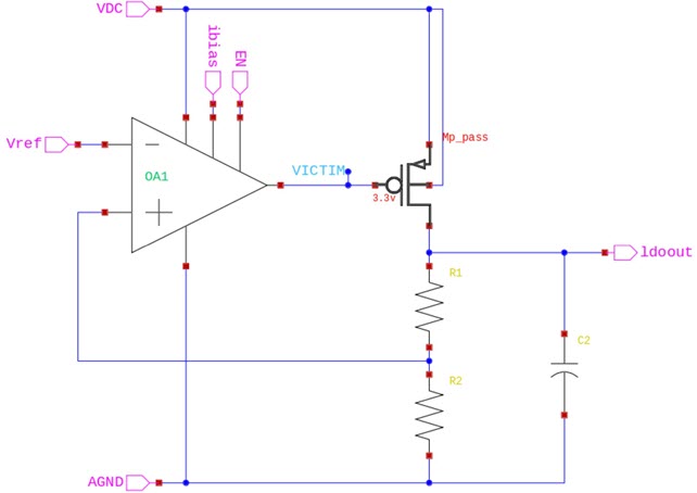
Because no node is perfectly isolated, leakage currents through the surrounding transistors will cause the voltage on this floating net to drift over time. This drift is the “silent killer.” If the voltage reaches the threshold of a connected transistor, it can inadvertently turn that device on. This can trigger a cascade of failures: unregulated power routing, latch-up conditions, or even permanent physical damage to the device or downstream components.
어떤 노드도 완벽히 절연되어 있지 않기 때문에, 주변 트랜지스터를 통과하는 누설 전류(leakage currents)로 인해 이 플로팅 넷의 전압은 시간에 따라 서서히 표류(drift)하게 됩니다. 이러한 전압 표류는 일종의 "소리 없는 암살자"와도 같습니다. 만약 전압이 연결된 트랜지스터의 임계값에 도달하면, 해당 소자가 의도치 않게 켜질 수 있습니다. 이는 비규제 전력 라우팅, 래치업(latch-up) 상태, 심지어 소자나 후단 부품에 영구적인 물리적 손상을 초래하는 연쇄적인 고장을 촉발할 수 있습니다.
Why SPICE is blind to structural defects
For decades, SPICE simulation has been the gold standard for analog verification. However, when it comes to floating nets, SPICE has a massive blind spot. There are three primary reasons why even the most rigorous simulation testbenches fail to catch these defects.
- The convergence artifact SPICE simulators are designed to find a numerical solution for circuit equations. When a simulator encounters a truly floating node, the matrix becomes singular, and the simulation fails to converge. To prevent this, simulators often use a technique called “gmin stepping,” which adds a very high-impedance resistor (typically ohms) from every node to ground. While this allows the simulation to complete, it inadvertently masks the floating net by providing a path to ground that does not exist in the actual silicon.
- The time-scale problem Floating net failures are often time-dependent. A node might take milliseconds or even seconds to drift to a critical voltage level. Standard functional simulations rarely run for this duration, as the computational cost would be prohibitive. Consequently, the defect remains hidden during the short windows typically analyzed during verification.
- Testbench coverage Detecting a floating net requires testing every possible combination of power-down states and sequences. In a complex SoC with dozens of power domains, the number of permutations is astronomical. It is statistically impossible to cover all these conditions using transient simulation alone.
수십 년 동안 SPICE 시뮬레이션은 아날로그 검증의 표준으로 자리 잡아 왔습니다. 그러나 플로팅 넷 문제에 관해서는 SPICE에도 치명적인 맹점이 있습니다. 가장 엄격한 시뮬레이션 테스트벤치조차 이러한 결함을 잡아내지 못하는 데에는 크게 세 가지 이유가 있습니다.
- 컨버전스 아티팩트 (The convergence artifact) SPICE 시뮬레이터는 회로 방정식의 수치적 해를 찾도록 설계되어 있습니다. 시뮬레이터가 진정한 의미의 플로팅 노드를 만나면 매트릭스가 특이(singular) 상태가 되어 시뮬레이션이 수렴하지 못합니다. 이를 방지하기 위해 시뮬레이터는 모든 노드에서 접지로 매우 높은 임피던스의 저항(보통 수옴 수준)을 추가하는 'gmin 스테핑'이라는 기법을 자주 사용합니다. 이 덕분에 시뮬레이션은 완료되지만, 실제 실리콘에는 존재하지 않는 접지 경로를 억지로 제공함으로써 플로팅 넷을 은폐하게 됩니다.
- 타임스케일 문제 (The time-scale problem) 플로팅 넷 결함은 종종 시간에 따라 다르게 나타납니다. 노드가 임계 전압 수준으로 표류(drift)하는 데 밀리초(ms) 또는 심지어 수초가 걸릴 수도 있습니다. 연산 비용이 지나치게 커지기 때문에 표준 기능 시뮬레이션은 일반적으로 이 정도 시간 동안 실행되지 않습니다. 결과적으로 검증 과정에서 분석되는 짧은 창(window) 동안에는 이 결함이 숨겨진 채 유지됩니다.
- 테스트벤치 커버리지 (Testbench coverage) 플로팅 넷을 감지하려면 전원 차단 상태와 시퀀스의 모든 가능한 조합을 테스트해야 합니다. 수십 개의 전원 도메인이 있는 복잡한 SoC에서는 경우의 수가 천문학적입니다. 과도 응답(transient) 시뮬레이션만으로는 이 모든 조건을 커버하는 것이 통계적으로 불가능합니다.
The “VICTIM” net: A case study in failure
Consider a common scenario in a high-performance analog block. An enable signal (EN) controls the power state of the block. When is low, the paths to both the supply (VDD) and ground (GND) are cut to eliminate static power consumption.
고성능 아날로그 블록에서 흔히 발생하는 시나리오를 생각해 보겠습니다. 인에이블 신호(EN)가 블록의 전원 상태를 제어합니다. EN이 로우(low)일 때는 정지 전력(static power) 소모를 없애기 위해 전원(VDD)과 접지(GND)로 향하는 경로가 모두 차단됩니다.
In one analyzed design, a specific net—internally labeled the “VICTIM” net—connected to the gate of a large PMOS pass transistor. When the block was enabled, the net was driven correctly. However, in power-down mode, the net was left entirely floating (Figure 2).
분석된 한 설계에서는 내부적으로 “VICTIM” 넷으로 명명된 특정 넷이 대형 PMOS 패스 트랜지스터의 게이트에 연결되어 있었습니다. 블록이 활성화되었을 때는 이 넷이 올바르게 구동되었습니다. 하지만 전원 차단 모드에서는 이 넷이 완전히 플로팅 상태로 방치되었습니다(그림 2).
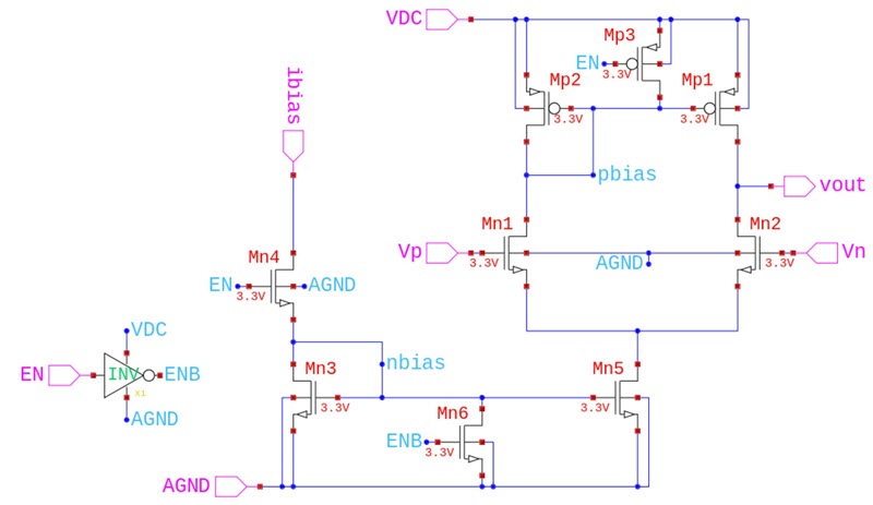
During simulation, the defect was masked by the simulator’s internal grounding. But in silicon, the trapped charge on the gate caused the pass transistor to partially turn on during a long idle period. This resulted in a massive current spike that damaged the output stage, leading to a costly field failure and a subsequent re-spin.
시뮬레이션 과정에서는 시뮬레이터 내부의 접지 처리(gmin 스테핑 등)로 인해 이 결함이 가려졌습니다. 그러나 실제 실리콘에서는 게이트에 갇힌 전하로 인해 긴 유휴(idle) 기간 동안 패스 트랜지스터가 부분적으로 켜지게 되었습니다. 이로 인해 막대한 전류 스파이크가 발생하여 출력 단자가 손상되었고, 결국 비용이 많이 드는 현장 고장과 그에 따른 재설계(re-spin)로 이어졌습니다.
Shifting reliability left with structural analysis
To address the limitations of simulation, the industry is moving toward automated structural analysis. Tools like the Calibre Insight Analyzer allow designers to “shift-left” their reliability verification by identifying structural defects based on the circuit’s topology rather than its transient behavior.
시뮬레이션의 한계를 극복하기 위해 업계는 자동화된 구조 분석(structural analysis)으로 이동하고 있습니다. 칼리버 인사이트 분석기(Calibre Insight Analyzer)와 같은 도구를 사용하면 설계자들은 과도 응답 동작이 아니라 회로의 토폴로지(위상 구조)를 바탕으로 구조적 결함을 식별함으로써 신뢰성 검증을 '시프트 레프트(shift-left, 개발 초기 단계로 앞당김)'할 수 있습니다.
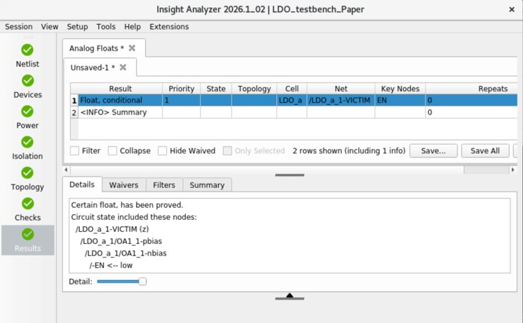
Structural analysis works by parsing the netlist and layout to build a complete map of the circuit’s connectivity. It then evaluates this map against all defined power modes. Unlike SPICE, which looks for functional output, structural analysis looks for the absence of a valid state (Figure 3).
구조 분석은 넷리스트(netlist)와 레이아웃을 파싱하여 회로 연결 상태의 전체 맵을 구축하는 방식으로 작동합니다. 그런 다음 이 맵을 정의된 모든 전원 모드와 비교하여 평가합니다. 기능적 출력을 확인하는 SPICE와 달리, 구조 분석은 유효한 상태의 부재 여부를 확인합니다(그림 3).
How to catch floating nets that simulation misses
Finding floating nets requires the use of a layout-aware circuit integrity analysis tool. For example, the Calibre Insight Analyzer tool doesn’t just look at the schematic; it accounts for the physical parasitics that contribute to charge trapping and drift. The tool follows a structured three-step process:
- Mode definition: The user defines the various power states of the design, including which signals are high, low, or high-impedance in each mode.
- Topological checking: The tool traverses the circuit graph to identify any node that lacks a low-impedance path to a supply or ground in any given mode.
- Reporting and visualization: Discrepancies are flagged and cross-probed back to the layout and schematic, allowing designers to quickly implement a fix—such as adding a high-impedance bleeder resistor or a tie-off cell.
플로팅 넷(floating net)을 찾아내려면 레이아웃 인식 회로 무결성 분석 도구를 사용해야 합니다. 예를 들어 칼리버 인사이트 분석기(Calibre Insight Analyzer) 도구는 회로도만 보는 것이 아니라, 전하 포획(charge trapping)과 표류(drift)에 기여하는 물리적 기생 성분까지 고려합니다. 이 도구는 다음과 같은 체계적인 3단계 프로세스를 따릅니다.
- 모드 정의 (Mode definition): 사용자는 각 모드에서 어떤 신호가 하이(high), 로우(low) 또는 고임피던스(high-impedance) 상태인지 포함하여 디자인의 다양한 전원 상태를 정의합니다.
- 토폴로지 검사 (Topological checking): 이 도구는 회로 그래프를 탐색하여 주어진 모드에서 전원이나 접지로 향하는 저임피던스 경로가 부족한 노드를 식별합니다.
- 보고 및 시각화 (Reporting and visualization): 문제점이 발견되면 레이아웃 및 회로도와 교차 프로빙(cross-probe)되어 설계자가 고임피던스 블리더 저항(bleeder resistor)이나 타이오프 셀(tie-off cell) 추가와 같은 수정 사항을 신속하게 구현할 수 있도록 지원합니다.
The path to signoff confidence
As we move toward 3D IC architectures and heterogeneous integration, the complexity of power delivery networks will only increase. The interdependencies between thermal profiles, mechanical stress, and electrical reliability mean that a single floating net can have catastrophic system-level consequences.
3차원 집적회로(3D IC) 아키텍처와 이종 통합(heterogeneous integration)으로 나아감에 따라, 전력 분배 네트워크(power delivery networks)의 복잡성은 더욱 커질 것입니다. 열 프로필, 기계적 응력, 그리고 전기적 신뢰성 사이의 상호 의존성은 단 하나의 플로팅 넷조차 치명적인 시스템 수준의 결과를 초래할 수 있음을 의미합니다.
Relying on legacy verification methods is no longer sufficient. Automated structural analysis is becoming a mandatory requirement for analog signoff. By integrating these checks early in the design cycle, engineering teams can move beyond the “silicon success crisis” and deliver high-performance, reliable products with confidence.
기존의 검증 방법에만 의존하는 것은 더 이상 충분하지 않습니다. 자동화된 구조 분석은 아날로그 최종 승인(signoff)을 위한 필수 요구사항이 되어가고 있습니다. 이러한 검증 과정을 설계 주기의 초기 단계에 통합함으로써, 엔지니어링 팀들은 "초도 웨이퍼 성공의 위기"를 극복하고 고성능의 신뢰할 수 있는 제품을 자신 있게 선보일 수 있습니다.
Conclusion: Moving from transient simulation to structural signoff
Floating nets are a structural reality of modern low-power design, but they don’t have to be a reliability risk. By understanding the limitations of SPICE and adopting automated structural analysis, designers can identify these silent killers before they ever reach the fab. Shifting reliability left isn’t just a best practice – it’s the only way to ensure silicon success in the advanced node era.
플로팅 넷은 현대 저전력 설계의 구조적 현실이지만, 반드시 신뢰성 리스크가 되어야 하는 것은 아닙니다. SPICE의 한계를 이해하고 자동화된 구조 분석을 도입함으로써, 설계자들은 이 '소리 없는 암살자'들이 팹(fab)에 도달하기 전에 미리 찾아낼 수 있습니다. 신뢰성 검증을 앞당기는 '시프트 레프트(shifting-left)'는 모범 사례일 뿐만 아니라, 첨단 노드 시대에 실리콘 성공을 보장하는 유일한 방법입니다.
About Bhanu Pandey:
Bhanu Pandey is a product engineer for Calibre Design Solutions at Siemens Digital Industries Software, with responsibility for the Insight Analyzer circuit reliability analysis tool. His focus and technical experience are in analog circuits.
바누 판데(Bhanu Pandey)는 지멘스 디지털 인더스트리 소프트웨어(Siemens Digital Industries Software)의 캘리버 디자인 솔루션(Calibre Design Solutions) 제품 엔지니어로서, 인사이트 분석기(Insight Analyzer) 회로 신뢰성 분석 도구를 담당하고 있습니다. 그의 주력 분야와 기술적 전문성은 아날로그 회로에 있습니다.